I’ve been longing for this day (/night) for almost an year now! I’ve finally, finally, got some data from an electret mic and finally got it into a beaglebone black. If you really want to understand the depth of this achievement, please go through what I’ve been doing for the past few months:
http://electronics.stackexchange.com/questions/111458/reading-sound-with-beaglebone-black
http://electronics.stackexchange.com/questions/111969/understanding-a-circuit-diagram
http://electronics.stackexchange.com/questions/106204/connect-electret-mics-to-computer
http://electronics.stackexchange.com/questions/77160/microphone-time-delay-estimation
http://dsp.stackexchange.com/questions/11399/signal-processing-using-panda-board
http://dsp.stackexchange.com/questions/11561/sound-card-for-recording-audio
http://dsp.stackexchange.com/questions/11472/audio-interface-or-external-sound-card
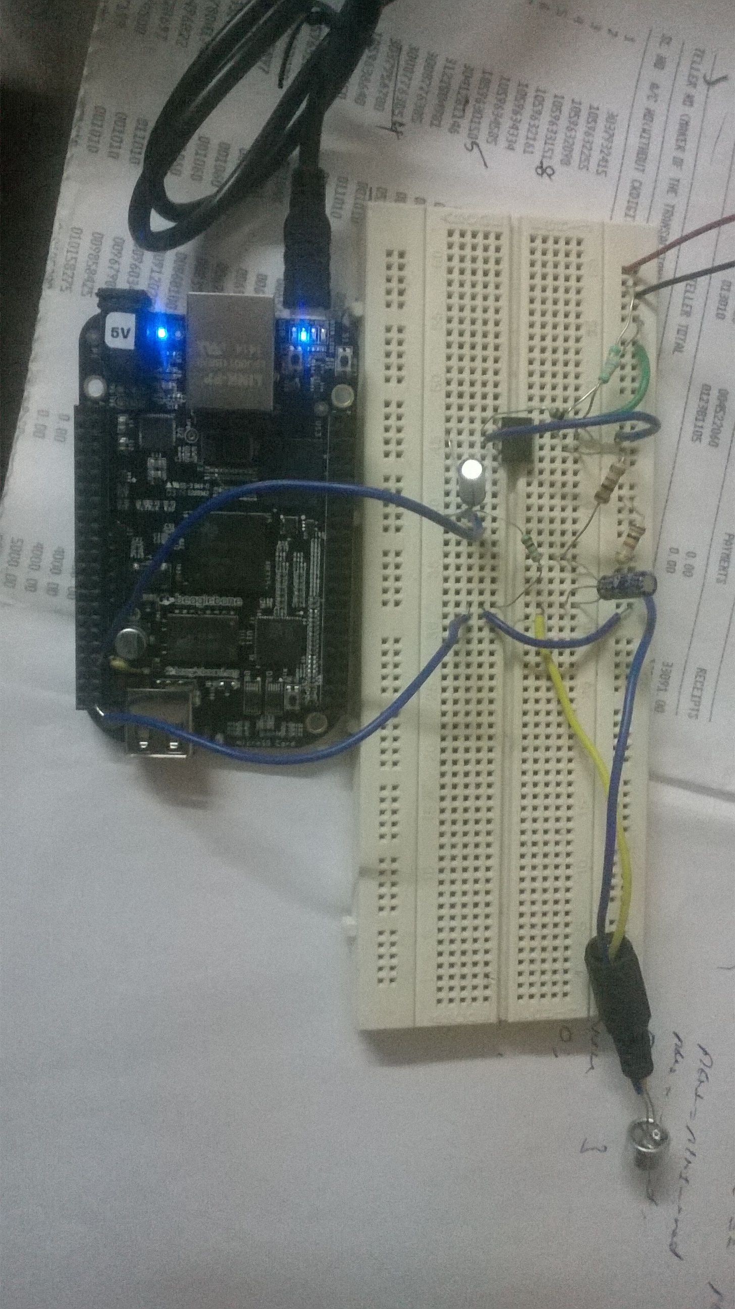
That’s a lot of questions. And I got a lot of answers. Though I’m no where near completing the actual project, at least getting it started is a relief. I’ve tried making my own amplifier, tried an audioboard from hrc, tried another opamp IC for amplifier, and finally hit upon this :
The previous amplifiers I made might have been working fine – I just might not have read the values properly. Anyways, its working now and that’s all I care about.
Components : Everything that was in the previous link containing the circuit diagram. I did not have 10 uF capacitors so I used 22 uF instead.
Beaglebone black : The INR 4200 beast. This board is being sold out faster than it is being produced. Lucky we could order one!
The process is pretty straightforward now that it works. The beaglebone black has a set of analog pins that can read analog inputs. I connect the mic (which produces voltage variations in the range of 20mv) to a preamplifier (built using the circuit diagram in the link and 741 opamp) and the output of the preamp (in range of 1 v) is given to the analog input of the BBB. When the sound hits the electret mic, it produces a voltage that is proportional to the amplitude of the sound. This is the signal we then amplify and finally measure.
Is this enough to do some signal processing and thus continue the project? Now that requires more experimenting and is a matter for another post.
I made the mistake of not connecting the ground of beaglebone black to the ground rail in the breadboard and cursed many perfectly working amplifier circuit because it BBB did not read.
Now we have to read this value using beaglebone.
First, enable the input output pins :
echo cape-bone-iio > /sys/devices/bone_capemgr.*/slots
If that step went well, you should not see any messages.
Then I wrote a small python script to read the analog pin 1 continously :
import os

import time
while 1:
os.system("cat /sys/devices/ocp.2/helper.14/AIN1")
time.sleep(0.1)
Replace AIN1 with your analog pin (for eg: AIN2 or AIN3) and the value in time.sleep with your desira
ble delay between reads. Saved it as test.py and python test.py does the job.

The beaglebone black can read only voltages till 1.8 volts on its analog pins. Also, it can only read DC. That is why there are a lot of 0s in my screenshot – that’s where the negative voltages should go. The solution is to give a DC bias to the analog signal. Say we give 1v bias. Then the readings would be around 1V and will go below 1v when a negative peak occurs.
